How to Wire a 12V Air Suspension Compressor Using a Relay
Wiring a 12V air suspension compressor is not complicated, but it does need to be done correctly. A compressor draws a lot more current than a normal switch circuit, especially when it first starts, so it should not be wired directly through a small dashboard switch.
The correct way is to use a relay. The dashboard switch, ignition live feed or pressure switch only has to control the relay. The relay then handles the heavier current needed to run the compressor.
This is the same basic wiring principle used on many of our On Board Air, or OBA, kits for vans, pickups, motorhomes and air suspension systems.
Why You Should Not Wire the Compressor Directly Through a Switch
A compressor is a high-current electrical load. When it starts, the current draw can be much higher than people expect.
If you wire the compressor directly through a small on/off switch, the switch may overheat, burn out, melt internally, fail, or in the worst case create a fire risk. Even if it works briefly, it is not good practice.
The switch should only be used to trigger the relay. The relay then switches the heavier current to the compressor.
In simple terms:
- The switch controls the relay.
- The relay controls the compressor.
- The fuse protects the wiring.
- The pressure switch controls when the compressor should run.
Why a Pressure Switch Is Needed
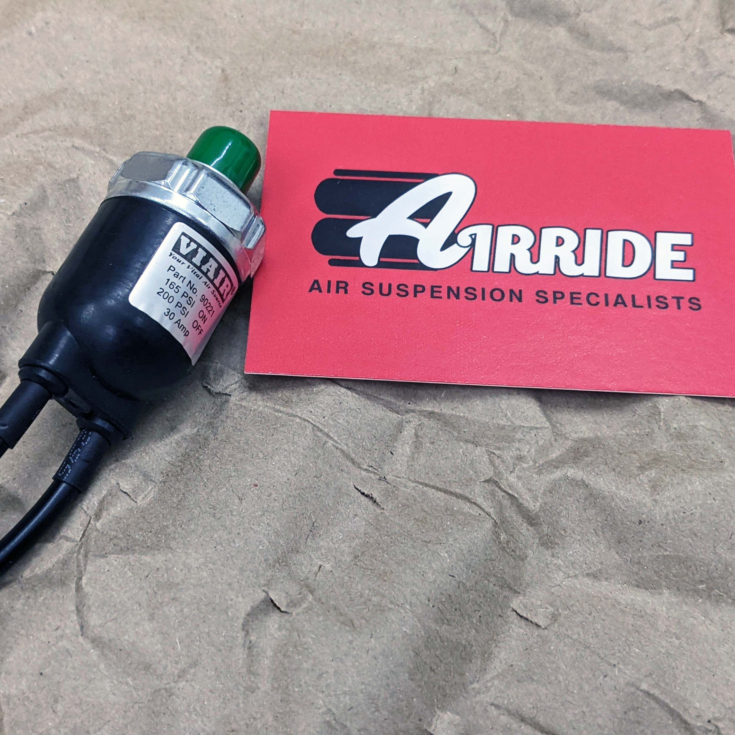
A pressure switch is what allows the compressor to turn on and off automatically.
Without a pressure switch, the compressor would simply keep running until you switched it off manually. That risks over-pressurising the tank, or in some systems, over-pressurising the bags depending on how the system is plumbed.
A normal tank-based onboard air system needs a pressure switch so the compressor cuts in and cuts out at sensible pressures. For example, a pressure switch might turn the compressor on at around 110 PSI and off at around 145 PSI.
The compressor should not be left to run without pressure control.
Why a Relay Is Used
A relay is simply an electrically operated switch. It allows a low-current circuit to control a high-current circuit.
That means you can use a small dashboard switch, ignition live supply, or pressure switch to control the compressor safely without sending the compressor's full current through those small control components.
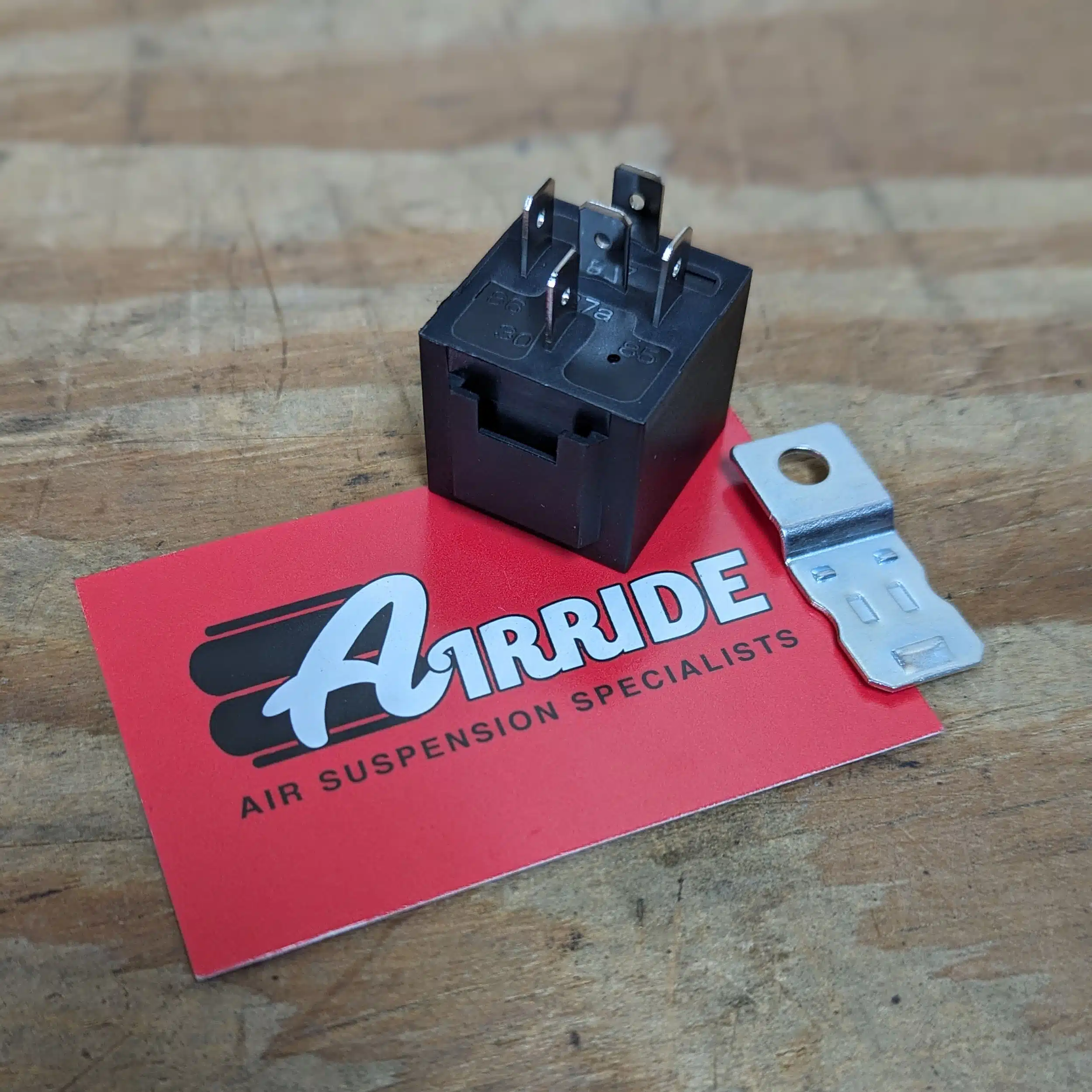
A standard automotive 30/40 amp 4-pin relay is commonly used for this type of compressor wiring.
The Four Relay Pins Explained
Most standard automotive 4-pin relays use terminals 30, 87, 85 and 86.
Pin 30 - Power In
Pin 30 connects to the positive battery supply through the main fuse.
This is the high-current power feed for the compressor circuit. The fuse should be fitted close to the battery so the cable is protected as early as possible.
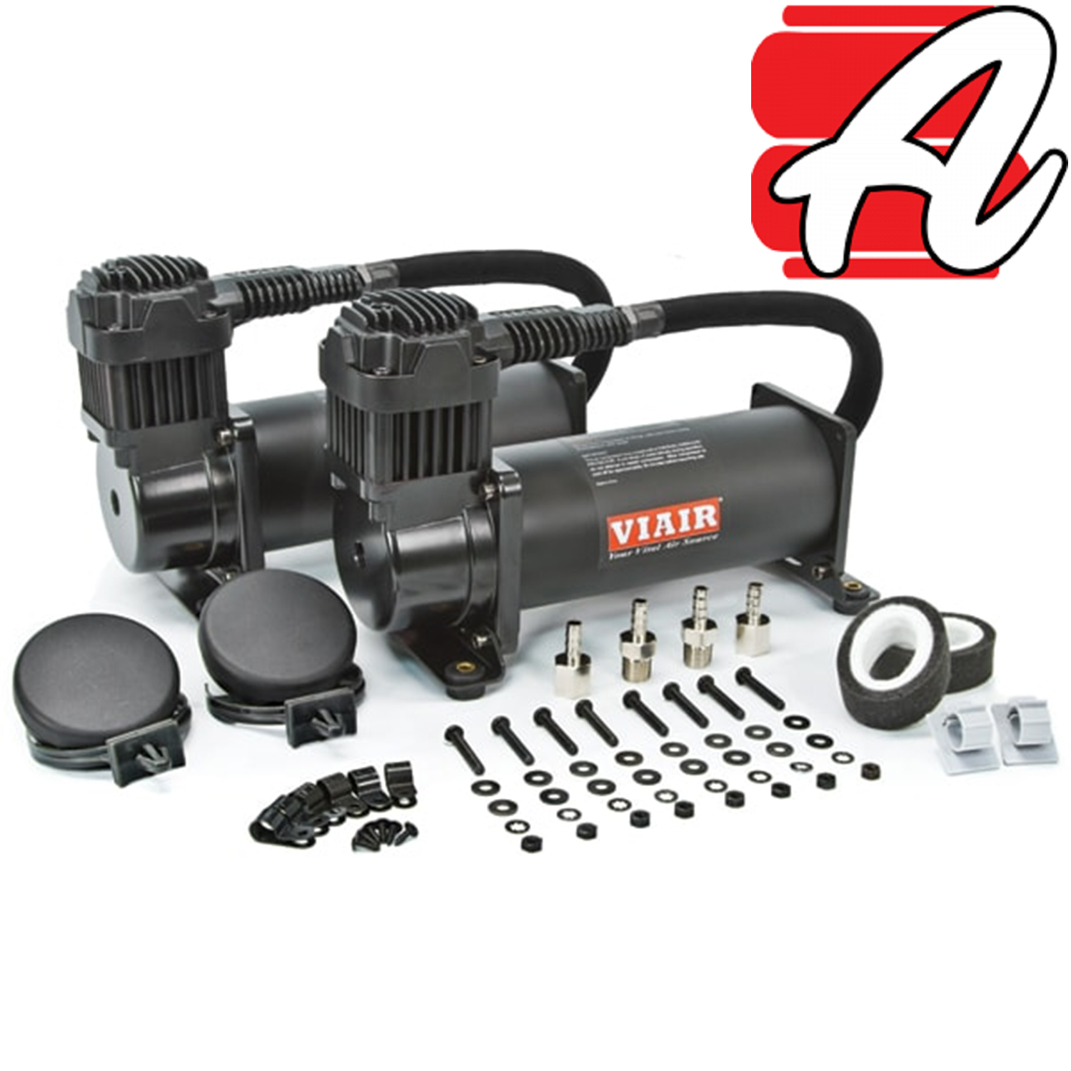
For a single Viair 12V compressor such as a 444C, a 30 amp fuse is commonly used, but always check the compressor specification and the instructions supplied with your kit.
Pin 87 - Power Out to Compressor
Pin 87 connects to the compressor positive feed.
When the relay is triggered, power flows from pin 30 to pin 87, then on to the compressor. On Viair compressors, this is normally the red compressor wire.
The compressor then needs a good earth connection from the black wire to the vehicle chassis or directly back to the battery negative.
A poor compressor earth is a very common cause of unreliable operation.
Pin 86 - Trigger Feed
Pin 86 is the trigger feed for the relay coil.
This can be supplied through a dashboard on/off switch, or in some installations from an ignition live feed. The purpose of this feed is to tell the relay when the system is allowed to operate.
Because this is only a relay trigger circuit, it does not need the same heavy cable as the compressor feed.
Pin 85 - Trigger Earth Through the Pressure Switch
Pin 85 completes the relay coil circuit to earth, usually through the pressure switch.
When tank pressure drops below the pressure switch cut-in point, the pressure switch closes the circuit to earth. This energises the relay, which then sends power to the compressor.
When the tank reaches the pressure switch cut-off pressure, the pressure switch opens the circuit and the relay switches the compressor off.
Pin 85 can be connected to a clean, unpainted chassis earth through the pressure switch, or taken back to the battery negative. Running it back to battery negative takes more wire, but can sometimes be more reliable, especially where chassis earth points are poor.
Why There Are Two Fuses
The diagram shows two fuses because there are two different parts of the circuit.
The larger fuse protects the compressor power feed. This is the high-current cable supplying power from the battery to relay pin 30, and then from relay pin 87 to the compressor. For many single compressor installations this is typically around 30 amps, depending on the compressor and wiring length.
The smaller fuse protects the control circuit. This is the lower-current side that supplies the on/off switch, pressure switch and relay trigger circuit. A 5 amp fuse is normally sufficient for this because it is only operating the relay coil, not powering the compressor itself.
Do not assume that one fuse protects everything properly. Each circuit should be protected according to the wire size and the current it is expected to carry.
Wire Size Matters
Correct wire size is important.
The compressor feed must use cable suitable for the current draw and the length of the run. A good rule of thumb is to use at least the same size cable as the compressor already has fitted. For a Viair 444C, this is likely to be around 14 gauge.
If the cable run from the battery to the relay or compressor is long, it may be sensible to go up a size. In American Wire Gauge terms, going up one size means the number gets smaller, so 12 AWG is larger than 14 AWG.
The trigger wiring for relay terminals 85 and 86 does not need to be as thick because it is only carrying the small current needed to energise the relay. In many cases, light automotive cable is fine. Speaker wire is electrically capable for low-current relay switching, although proper automotive cable is neater and generally preferred for vehicle work.
Single Compressor or Twin Compressors?
The diagram is for a single 12V compressor.
If you are running two compressors, do not simply double everything onto one relay without checking the current draw. The better method is normally to use two relays, with each compressor having its own properly fused power feed and relay-controlled supply.
Twin compressor systems need more care because the current draw is much higher. Fuse size, cable size, relay rating and earth quality all become even more important.
On/Off Switch or Ignition Live?
The diagram shows a manual on/off switch. This allows you to enable or disable the compressor system.
In some installations, this can be replaced or supplemented by an ignition live feed so the compressor only runs when the vehicle ignition is on. That can be useful because it prevents the compressor running unexpectedly when the vehicle is parked.
The best arrangement depends on the vehicle and how the air system is used. For many onboard air and air suspension systems, having a clear manual isolation switch is still useful.
Good Earths Are Essential
A weak earth can cause all sorts of problems. The compressor may run slowly, fail to start, blow fuses, overheat wiring, or behave inconsistently.
All earth points should be clean, solid and secure. Remove paint, rust and dirt where needed, use proper terminals, and make sure the connection cannot work loose.
Where possible, earth cables should be short and direct. For critical circuits, running a dedicated earth back to the battery negative can be more reliable than relying on a questionable chassis earth.
Use Proper Terminals, Crimpers and Protection
A wiring diagram is only part of the job. The quality of the actual installation matters just as much.
Use proper terminals, good crimpers and heat shrink where appropriate. Poor crimping is one of the most common causes of electrical faults. A crimp should be mechanically secure and electrically sound, not just squeezed flat with pliers.
All wiring should be secured properly with cable ties or clips and protected with conduit where it passes under the vehicle or near moving parts.
Do not allow wires to chafe against metal edges. If a wire passes through a hole, use a grommet. If it runs near heat, sharp edges, suspension movement or road debris, protect it properly.
Basic Wiring Summary
For a standard single compressor relay setup:
- Battery positive feeds the 30 amp fuse.
- The 30 amp fuse feeds relay terminal 30.
- Relay terminal 87 feeds the compressor positive wire.
- The compressor negative wire goes to earth or battery negative.
- Battery positive also feeds the 5 amp fuse for the control circuit.
- The 5 amp fuse feeds the on/off switch.
- The on/off switch feeds the pressure switch.
- The pressure switch feeds the relay trigger circuit.
- Relay terminal 86 and 85 form the relay coil circuit.
- Relay terminal 85 or 86 must complete to earth depending on the exact wiring layout used.
- The pressure switch controls whether the relay is energised.
- Good earths are essential.
The exact wiring layout can vary slightly depending on whether the pressure switch is switching live or earth, but the principle is the same: the relay handles the compressor current and the switch circuit only controls the relay.
Final Thoughts
Wiring a 12V compressor is simple enough, but it is not something to guess. Use the correct fuse ratings, correct wire size, a proper relay, good earths and secure connections.
Do not wire the compressor directly through a small switch. Do not omit the pressure switch. Do not leave wiring loose under the vehicle. Do not allow wires to rub through on metal edges.
Done properly, a relay-controlled compressor circuit is reliable, simple and easy to understand. Done badly, it can cause endless faults or become unsafe.
This principle applies to many of our On Board Air kits for vans, pickups, motorhomes and air suspension systems. If you are unsure which compressor, pressure switch, relay or wiring arrangement is right for your system, please get in touch before cutting wires.